Digital circuits serve as the foundation of modern electronics, powering everything from smartphones to spacecraft. However, these intricate circuits are not immune to issues. When problems arise, engineers rely on a critical tool in their toolkit: the logic analyzer. In this post, we will explore how logic analyzers are an incredibly useful tool for addressing problems in digital circuits.
How Do Logic Analyzers Work?
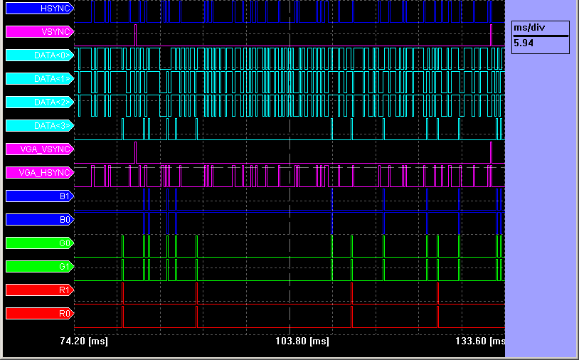
Logic analyzers (such as the portable TLA714 from Tektronix) work by capturing and displaying multiple digital signals simultaneously. They are able to do this by using a bank of comparators to compare each signal to a threshold voltage. The comparator outputs a high signal if the input signal is above the threshold voltage, and a low signal if the input signal is below the threshold voltage. The logic analyzer then samples the outputs of the comparators at a regular interval. This sampling rate is typically much higher than the frequency of the signals being captured, so that the logic analyzer can accurately capture even very short glitches.
The logic analyzer can also be used to trigger on specific events or conditions. This allows the user to focus their analysis on a specific part of the circuit or on a specific event. For example, the user could trigger on a specific bus transaction or on a specific interrupt signal.
Why Use a Logic Analyzer?
Logic analyzers are useful for troubleshooting digital circuits in a number of ways. They can capture and display multiple signals at the same time, allowing the user to see the timing relationships between different signals in a circuit, which can be very useful for identifying timing errors. They can trigger on specific events or conditions– allowing for focus on a specific part of the circuit. For example, triggering on a specific bus transaction or on a specific interrupt signal.
Logic Analyzers can also be used to measure the frequency and period of signals. This can be helpful for identifying clock errors, or for measuring the performance of a circuit. They can also be used to compare signals against expected values or patterns, which is helpful for verifying that the circuit is working as expected.
Overall, logic analyzers are very versatile tools that can be used to troubleshoot a wide variety of problems in digital circuits. They are an essential tool for any engineer who designs or develops digital systems.
Practical Applications
By capturing and analyzing data from multiple signals simultaneously, logic analyzers can help engineers and technicians identify the root cause of problems and develop solutions. From elusive timing problems to perplexing glitches, let’s explore how these versatile tools can help address a spectrum of challenges.
Identifying a Timing Problem: Logic analyzers like the TLA6202 from Tektronix step in by comparing the timing of a clock signal to that of a data signal. Anomalies, like improper data setup and hold times, become evident through the analyzer’s trace.
Spotting a Glitch: The keen eye of a logic analyzer can identify glitches by pinpointing short signal spikes. These glitches may arise from noise on the signal line or circuit design flaws. The analyzer’s precision in capturing and displaying signal data makes identifying these transient anomalies feasible.
Detecting Bus Contention: Logic analyzers shine in revealing bus contention scenarios, where multiple devices vie for bus control simultaneously. Analyzers with unlimited channel grouping such as the Tektronix TLA6204 can be especially helpful when pinpointing this competition.
Debugging a Microprocessor: When debugging a microprocessor, logic analyzers capture and dissect the executed instructions. This process aids in pinpointing errors within the microprocessor’s software or hardware.
Hardware Defects: Identifying hardware defects is another forte of logic analyzers. By comparing signals from a suspected defective component to those from a known good component, these tools help engineers isolate faulty hardware elements with precision
Detecting Electromagnetic Interference (EMI): Logic analyzers are adept at detecting EMI problems by scrutinizing signal lines for noise. EMI issues often stem from nearby electrical or electronic devices. The analyzer’s capability to identify these noise sources contributes to interference mitigation.
Tracking Environmental Factors: Logic analyzers extend their reach to monitor environmental factors such as temperature, humidity, and vibration levels in the vicinity of the circuit. These factors can influence digital circuit performance or even lead to complete failure. By tracking environmental conditions, logic analyzers aid in preemptive troubleshooting.
Tips and Best Practices for Effective Troubleshooting
Here are some tips and best practices for successful troubleshooting with logic analyzers:
● Document your findings and changes during the debugging process.
● Emphasize the importance of collaboration with team members, leveraging collective expertise.
● Highlight the value of patience and persistence, especially when dealing with intermittent issues.
Logic analyzers are wonderful tools to debug and troubleshoot digital circuits. By understanding how to use logic analyzers effectively, engineers and technicians alike can save time and money by identifying and fixing problems early in the development process.